Commissioning the BEAM-TM-L
Before you begin
- GW 3.6.1 powered on with the LoRa antenna connected.
- Project loaded into Nimbus 2.0 (no project needs to be created on Snape 2.0).
- Fresh battery installed in the TM-L node.
- OTG adapter and USB-C cable ready (not Micro USB).
- Android device (8.0+) with Ackcio Nimbus 2.0 installed.
Notice · Before mountingDecide whether Dynamic Monitoring will be enabled before you mount the node: it sets the required orientation. See Installing the BEAM-TM-L.
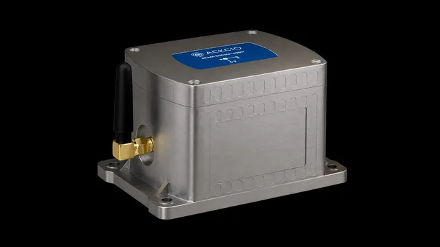
Step-by-step commissioning
Follow the green arrows in each screenshot.
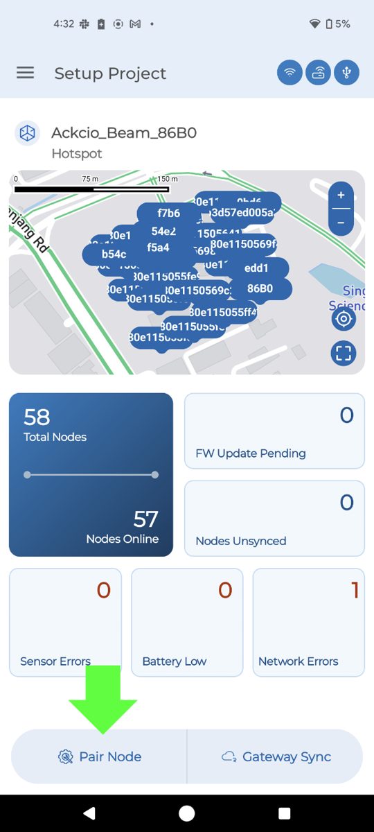
1Pair the node
Connect the USB-C cable from the TM-L to your Android device via the OTG adapter. Turn on the TM-L, press OK on the permission popup, then tap Pair Node within 10 seconds.
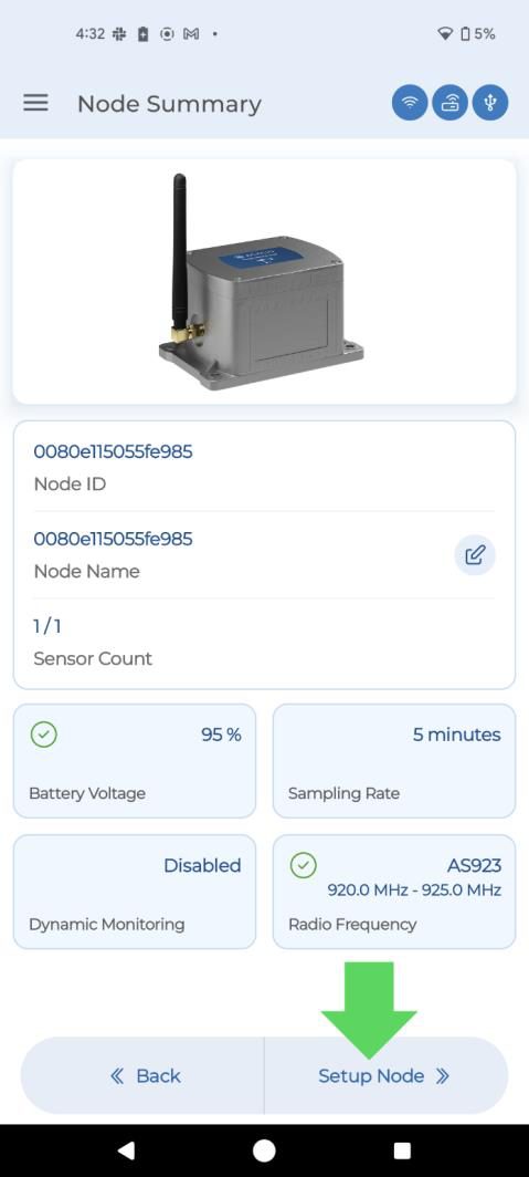
2Node summary
Review the node details: Battery Voltage, Radio MHz and Frequency. Tap SETUP NODE to proceed.
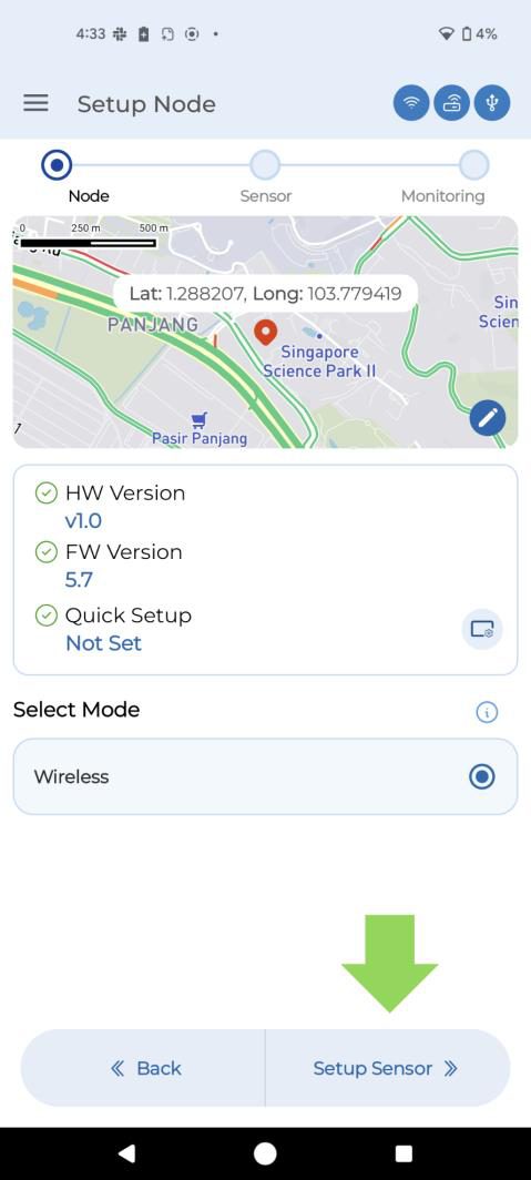
3Setup sensor
The sensor is built into the TM-L, so no external wiring is needed. Tap SETUP SENSOR to continue.
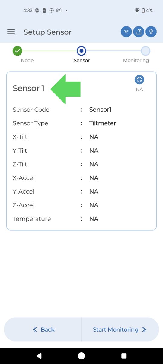
4Select Sensor 1
Tap Sensor 1 to begin configuring the TM-L sensor settings.
5Name the sensor
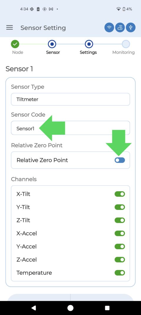
Enter a unique name under Sensor Code. Toggle Relative Zero Point ON if readings should start from 0 at installation. Tap Save.
6Configure channels
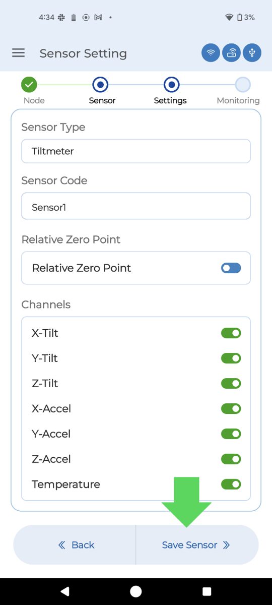
Enable or disable individual channels (X, Y, Z tilt and acceleration) as required. Tap SAVE SENSOR to apply.
7Verify live reading
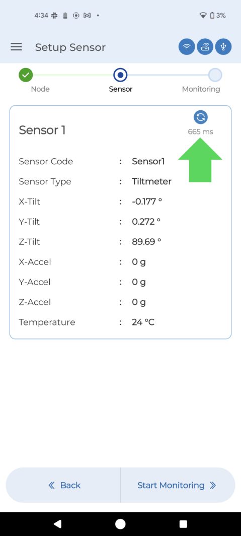
Tap the blue refresh icon to trigger a live sensor reading and confirm the sensor is responding correctly.
8Set sampling rate & dynamic monitoring
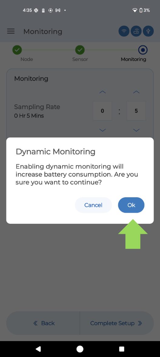
Set the Sampling Rate. If Dynamic Monitoring is required, enable it here: a popup will warn about increased battery consumption. Tap OK to confirm.
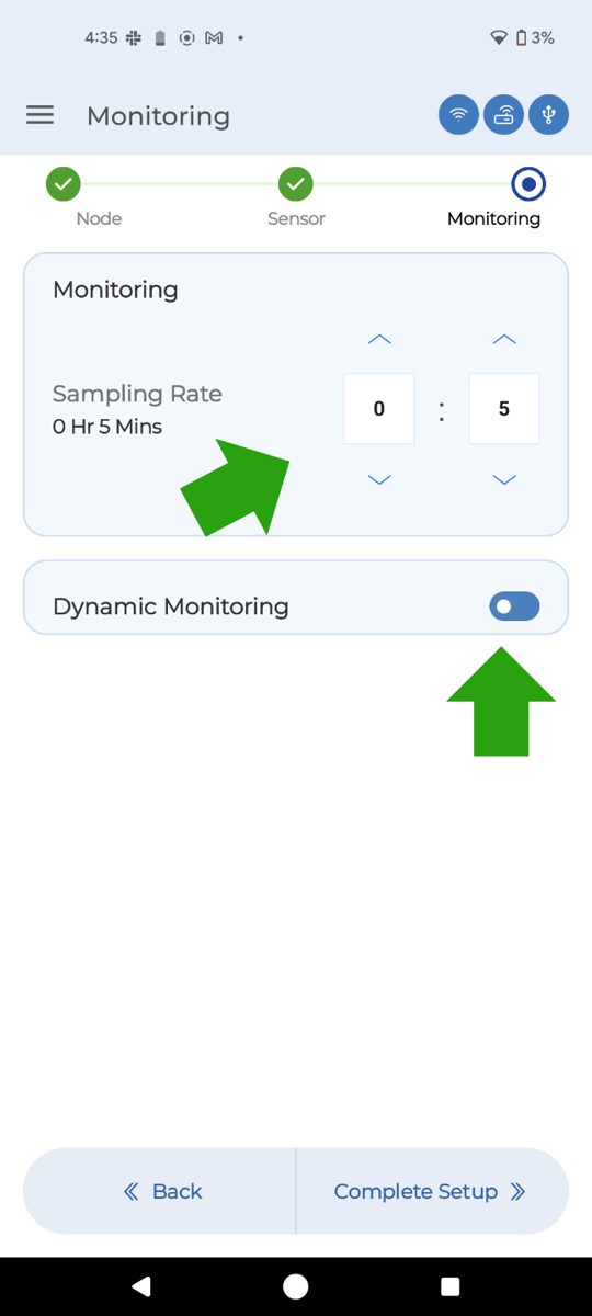
NoticeIf Dynamic Monitoring is enabled, ensure the node is already installed flat or using the wall bracket before deploying.
9Configure alarm thresholds
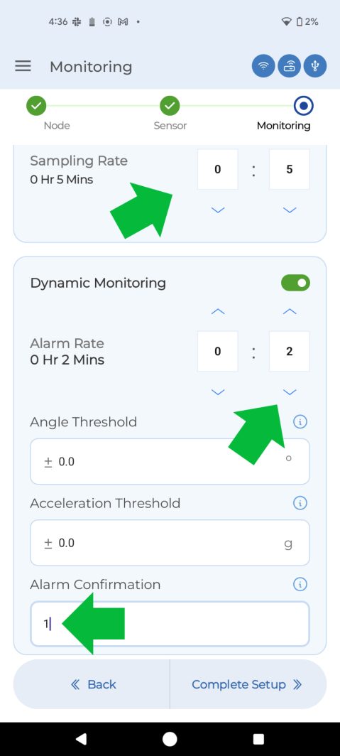
Set alarm thresholds. The mandatory sequence is: Sampling Rate > Alarm Rate > Alarm Confirmation. Set the angle and acceleration threshold accordingly. See Dynamic monitoring & alarms.
10Complete setup
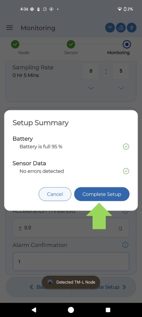
Once both checks (Battery and Sensor Data) are green, tap COMPLETE SETUP to finalise commissioning.
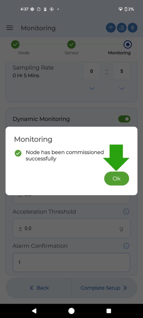
11Node goes online
Tap OK to finish. Ensure Auto Sync has happened; otherwise connect the Nimbus app to the GW Wi-Fi hotspot or remote.it link and do a Manual Sync. Monitor the Snape dashboard: the node should appear online within 10 to 15 minutes.
Did you know?Ensure line-of-sight (LOS) to the GW 3.6.1 gateway. Keep the GW and BEAM-TM-L in a static position while waiting for the node to appear on the Snape dashboard: moving them around delays the TM-L connecting to the gateway.
ImportantThe TM-L has no internal memory. If the battery dies after commissioning, any data not yet transmitted to the gateway is permanently lost. Check battery status regularly on the Snape dashboard.