Wire and set up a BEAM-DG node
 Commissioning videos16 BEAM-DG sensor videosGeokon, Yieldpoint, MDT, RST and more →
Digital Node: RS485 / SDI-12 Digital Sensors
The BEAM-DG (Digital Node) supports a wide range of digital sensors via RS485, RS232 and SDI-12 communication protocols. It is the most versatile node in the Ackcio range and is commonly used with advanced geotechnical instruments from leading manufacturers.
Supported Digital Sensor Brands & Protocols
- All Sisgeo digital sensors (RS485)
- All YieldPoint digital sensors and the YieldPoint dMUX (RS485/RS232)
- All Generic SDI-12 sensors: e.g. Campbell Scientific, Encardio, Climavue50, Maximet
- Geogage RS485 sensors (e.g. tiltmeters)
- Geokon RS485 sensors (e.g. IPIs, In-Place Inclinometers)
- Geosense RS485 sensors (e.g. tiltmeters, IPIs)
- RST RS485 sensors (e.g. tiltmeters, IPIs)
- ZC RS485 sensors (e.g. tiltmeters, IPIs)
- MDT SMARTLINK sensors: Sloughmeter & MPBX, addressable Smartlinks (up to 6 per node) and non-addressable Smartlinks (only 1 per node)
Step 1: Wiring Your Sensor to the BEAM-DG Node
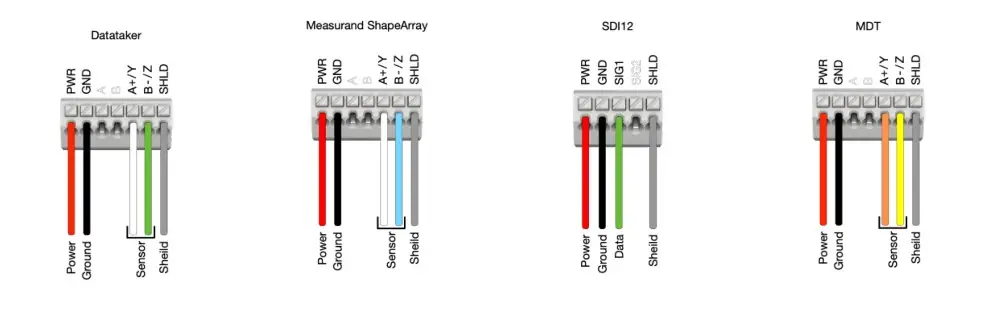
Connect your digital sensor's wires to the BEAM-DG Node's terminal blocks. The DG node has dedicated RS485, RS232 and SDI-12 ports with clearly labelled terminals. Refer to the wiring diagrams below that correspond to your sensor type.
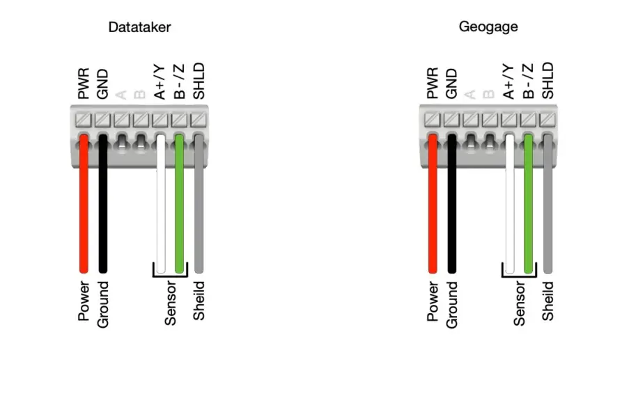
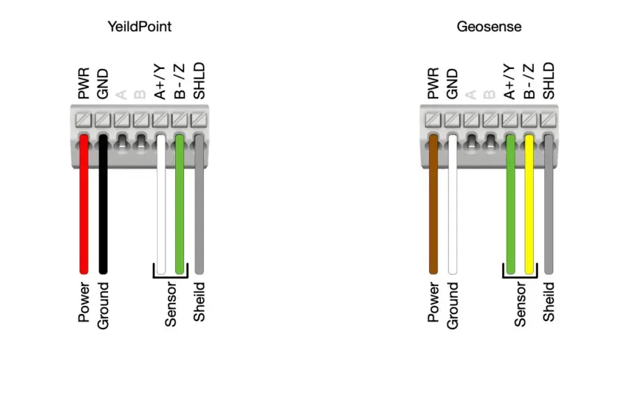
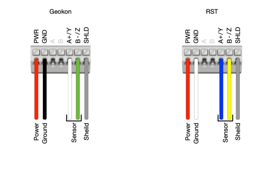
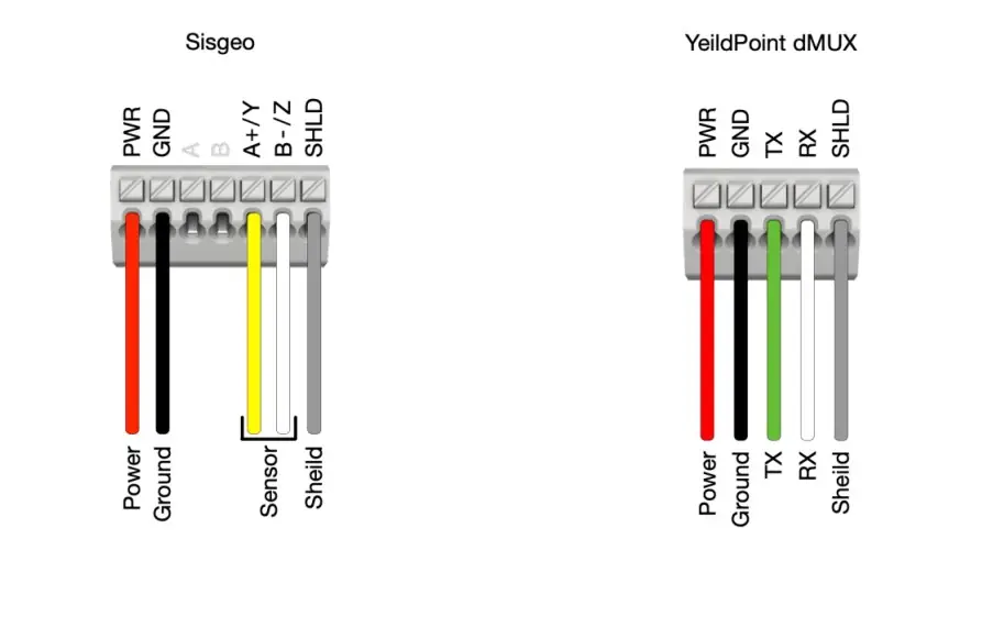
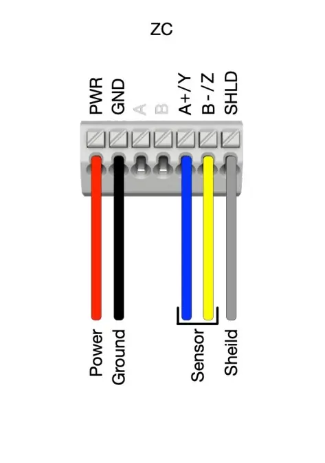
Step 2: Installing Sensor Firmware & Configuring in Nimbus
As BEAM-DG nodes support multiple sensor manufacturers, each with unique digital protocols, the correct manufacturer firmware must be flashed to the node before commissioning. Follow this sequence precisely:
1. Connect the BEAM-DG node to your Android device via Micro-USB (ensure OTG is enabled in Android settings).
2. Open the Nimbus app and navigate to the Setup Sensor page for the DG node.
3. Select the correct manufacturer firmware for your sensor (e.g., Sisgeo, YieldPoint, Geokon, SDI-12 Generic). Tap Install Firmware and wait for completion, Commissioning Video for each sensor manufacturer with guides to install specific manufacturer FW
4. Once firmware is installed, connect the sensor cables to the node's terminal blocks as per the wiring diagrams above.
5. Configure the sensor: assign a Sensor Code, select the correct sensor model, and set/fetch the address or set channel as required.
6. Trigger a live reading to verify the sensor is communicating correctly. Confirm values are within expected range.
7. Once verified, tap Start Monitoring, clear flash memory if prompted, set sampling rate, and tap Save. Ackcio has created dedicated commissioning videos for each supported DG sensor brand. These videos include photos of actual sensor connections for your reference:
DG Commissioning Videos: Google Drive Folder