Wire and set up a BEAM-VW node
 Commissioning videoBEAM-VW-S1: PiezometerWatch on YouTube ↗Commissioning videoBEAM-VW-S8: Piezometer, strain gauge, crackmeterWatch on YouTube ↗
Vibrating Wire Node: Strain Gauges / Piezometers / Crackmeters
The BEAM-VW (Vibrating Wire Node) is compatible with virtually all vibrating wire sensors on the market, including strain gauges, load cells, piezometers, crackmeters, and settlement cells. The node reads sensor frequency (Hz) and optionally temperature from a built-in thermistor.
Step 1: Wiring Your Sensor to the BEAM-VW Node
Connect your vibrating wire sensor cables to the BEAM-VW Node's terminal blocks as shown. VW sensors typically have 2 (coil) wires and optionally 2 additional thermistor wires. Match wire functions to the terminal labels carefully.
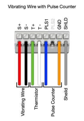
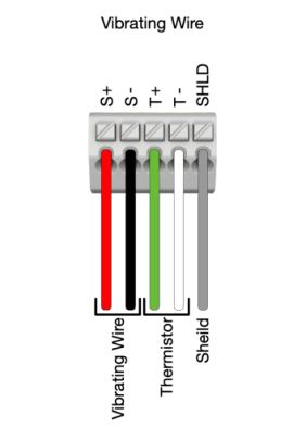
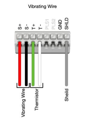
BEAM-VW Wiring Configurations: Standard VW, VW with Thermistor, Multi-channel VWS8
Step 2: Configuring the BEAM-VW Node in Nimbus
After wiring your sensor, open the Ackcio Nimbus app and navigate to the Setup Sensor page. For VWS8 nodes, you will see up to 8 sensor configuration boxes, configure each connected channel individually.
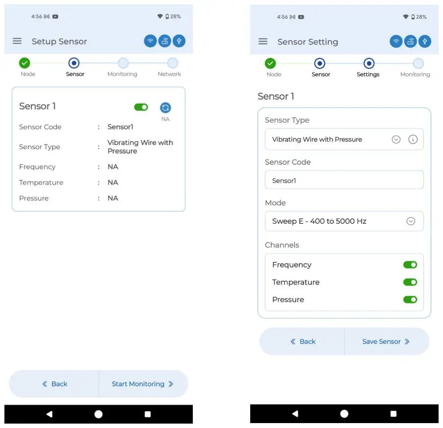
Nimbus: Sensor setup list (left) and Sensor Type/Sweep selection (right)
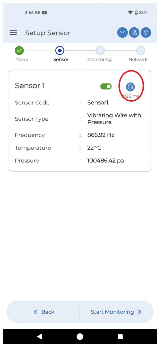
Nimbus: Triggering for live reading from VW sensor by pressing the Blue Refresh icon
1. On the Setup Sensor page, tap on Sensor 1 (or the relevant sensor box for VWS8) to begin configuration.
2. Tap Sensor Type and select the appropriate type: Vibrating Wire (for strain gauges, crack meters), Vibrating Wire with Rain Gauge, or Vibrating Wire with Pressure (for piezometers).
3. Tap Sensor Code and assign a descriptive name (e.g., 'Piezometer_CH1'). You may also leave it as the default (Sensor1, Sensor2, etc.).
4. Tap Mode and select the appropriate Sweep Mode based on your sensor's expected frequency range:
- Sweep A: 450 to 1200 Hz
- Sweep B: 800 to 2600 Hz
- Sweep C: 1400 to 3500 Hz
- Sweep D: 2400-6000 Hz
- Sweep E (Universal): 400 to 5000 Hz, use if unsure. Note: this consumes slightly more battery.
- Sweep F: 1400-3500 Hz
- Sweep G: 2800-4500 Hz
- Sweep H: 400-1200 Hz
- Sweep I: 1200-2800 Hz
- Sweep J: 2500-4500 Hz
- Sweep K: 800-1600Hz
5. Enable or disable the Temperature channel based on whether your sensor includes a thermistor. Disable unused channels, particularly on VWS8, to prevent error codes on unconnected ports.
6. Tap Save Sensor. The SENS LED on the node will begin blinking as it reads the sensor.
7. Tap the Blue Refresh icon to trigger a live test reading. Confirm the frequency reading is within the expected range for your sensor type.
8. Tap Start Monitoring once readings are verified.
9. Clear flash memory if prompted (recommended for fresh commissioning), set your sampling rate, and tap Save.